I am still patiently waiting for 3 major items to come in. Crankshaft, Cylinder Head and Exhaust System. The crankshaft is holding up the assembly of the engine bottom end, primary drive and final re-design of the rear engine plates. Once it is here I am also ready to fit the cylinder head and once that is done the exhaust system & carburettors. Then we are getting close.
The crank is still in Canada, awaiting balancing, nitriding and polishing. Should be here in a week or two. The cylinder head is being cast in Australia. I buy it from a Swede called Matt but who has his company in the USA, called Colorado Norton Works. Once he gets the head he will send it to Jim Comstock of Comstock Engineering. Jim will do the porting work and fit valves, springs and all that good stuff and then it will be sent off to me. My guess is I will get it in April. Maybe May. Once the head is in place I can also hook up the exhausts and whatever else is still on the to-do-list.
I took some pictures today of some of the goodies that will later be either buried inside the engine or just generally out of sight. Here we go:
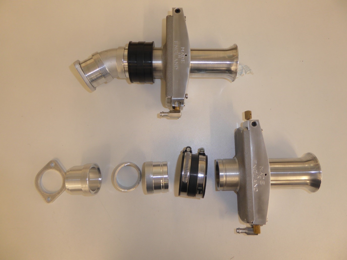
These are the carburettors. Gardner flat slide jobs with a bore diameter of 38 mm. The 4 pieces to the left have been designed by yours truly. The flange to the left is cut out with a laser beam of a 5mm aluminium plate. The next piece is fitting inside the flange and has an entry ID of 33 mm, exactly matching the cylinder head inlet port, over its 25 mm length tapering up to 34 mm. Turned by my friend Werner here on his CNC lathe. The next piece is a tube bend. This one made out of an aluminium 90 degree tube bend bought ready made. When it arrived I realized that it was not quite round, the diameter varying between 33 and 35 mm. Werner has tried to make it round but I am not happy. Googling a bit I found a local company that do 3D printing. I sent them a drawing and got an offer by return email. They are now on it and will deliver next week. The next part is 25 mm long and has an internal taper that takes the diameter from 34 to 36mm. Next is a rubber connector that clamps to the inlet tract and the carburettor. The carb at last has an entry diameter which opens up to 38mm at the flat slide.
Coming Saturday I will bring all 4 x 2 parts to a local guy that will weld them all together. The top of the picture shows what it will look like once done.
Next are some real goodies:
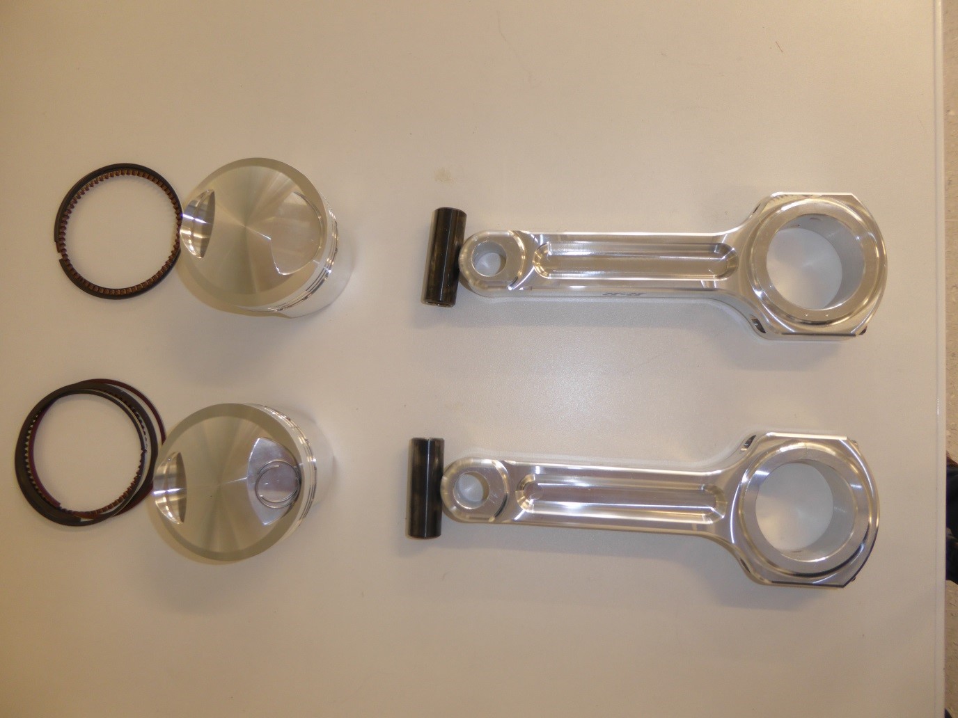
Piston rings to the left. Next come the forged high compression pistons ( I am shooting for about 11,5:1 which should be OK to run without the fuel detonating). Next are the piston pins, They have a DLC ( Diamond Like Coating ) which would allow them to run in steel connecting rods without using a small end bushing. As I am using connecting rods made of aluminium I don´t need DLC but now I have it anyway. Last but not least are the connecting rods. These are made from wrought aluminium alloy and then milled to size on a CNC machining centre. Made by R&R in Florida.
The rods are 6.400″ long (.525″ longer than standard Norton rods), increasing the length of rod-to-stroke ratio from 1.67 to 1 (stock 750) to a more ideal ratio of 1.83 to 1. The advantages of a longer rod are:
A) More power: The increase in power is a result of more dwell time at the top of the compression stroke, allowing more time for the fuel charge to burn completely and exert maximum force on the piston throughout the power stroke, This translates to more power for the amount fuel burnt.
B) Less Vibration: More dwell time at the top and bottom of the piston strokes means less “snap” due to the pistons not having to stop and reverse direction as quickly and abruptly as they would with a shorter rod.
C) Less stress full wear: The longer rod has less angle when traveling through mid-stroke than the short standard length rod. This means that less side forces are being applied to the cylinder wall – thus reducing friction, heat and wear.
For example: When a standard Norton crank is at 30 BTDC the distance from piston crown to TDC with the longer rod is 6.8mm compared to 9.2 mm with standard rods. So both sets of pistons are going from 6.8 and 9.2 mm BTDC to TDC in the same amount time. You can see that the piston with the longer rod spends more time closer to TDC (more efficient burning & power) and is moving slower when it reverses direction (less vibration).
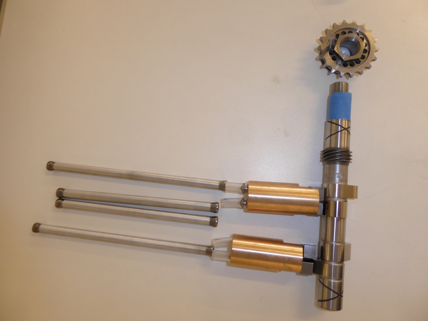
Next shows the aluminium pushrods left, then the cam follower housings made of brass, then the trick 270 degree camshaft. Above this the Vernier coupling that will allow me to dial in the valve timing to exactly where I want it. Nice piece made by RGM in the UK.
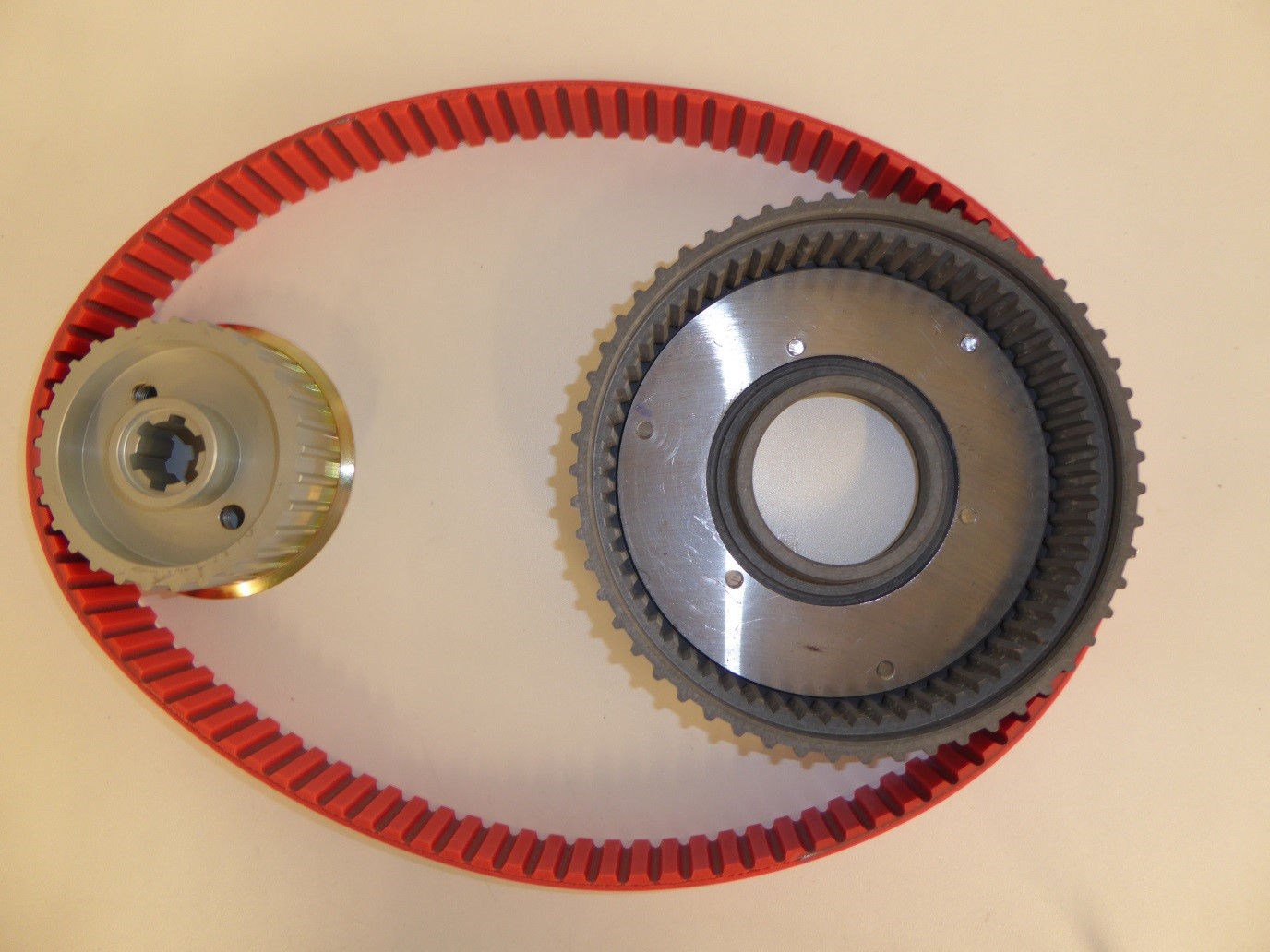
Here is the primary drive. A 29 tooth engine sprocket made of aluminium, as well as the 55 tooth clutch basket, and the 10 mm pitch drive belt.
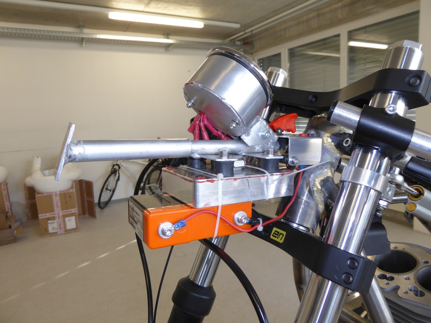
Below is the Ignition Control Unit, square rubber mounted aluminium box and tied to it the battery.
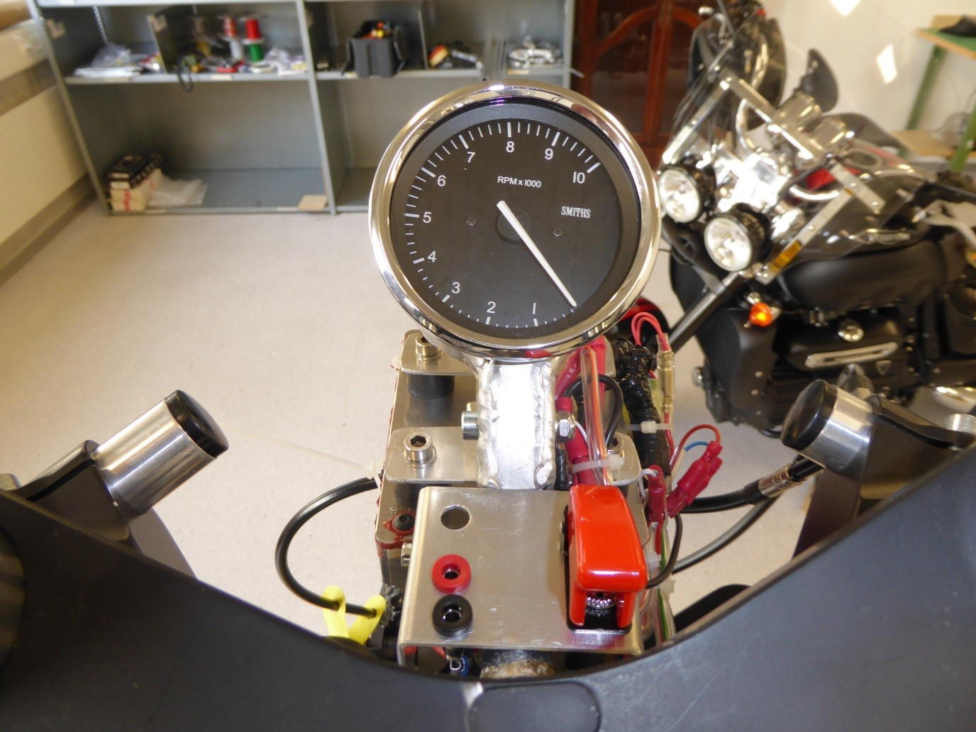
This is the driver´s view of the Tachometer etc.
The red plastic cover to the right is the safety cover for the ignition switch. The red and black plugs to the left are the connectors for the battery charger. The empty hole is – an empty hole. Mistake in the design/manufacturing process……
